")
")

Diaphragm valve
Technical Description
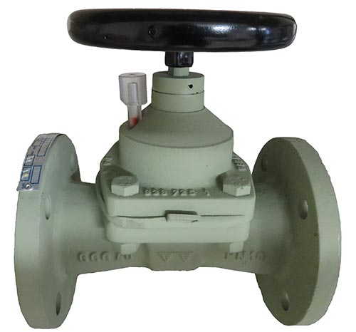 Diaphragm Gate Valve rubber lined, with a smooth through pass. This construction combinates all positive characteristics of diaphragm and gate valves. The cavity reduced design, the current optimized through pass and a lot of different variable body linings are suitable for fibrous and abrasive media. The closing element is made of soft rubber with a vulcanized steel core. The complete body is hard rubber lined and separated from the frame cover by a softly Diaphragm. Other materials for diaphragm and body linings are alternatively available.
Area of applications:
For non aggressive liquids and gases. DIN 2401 determines the admissible operating pressure, in relation to the temperature.
Variants:
- rubber lined/ enamel lined/ EKB lined
- without lining
- resilient seated
- metal seated
- ceramic lined
Diaphragm valve A20a / A20w
Nennweitenbereich DN 15 - DN 350, PN 10, Ausführung stopfbuchslos, mit nicht steigender Spindel
Flansche nach DIN 2501 PN 10 - weitere auf Anfrage
Baulänge nach ISO 5752 EN558-1 Reihe F1 / DIN 3202 Reihe F1.
Technische Lieferbedingungen und Prüfungen nach DIN 3354, Teil 1, und DIN 3230 AG, BA, BN
Merkmale
- Freier glatter Durchgang, geringer Druckverlust
- nach außen vollkommen dicht durch Membranahdichtung der Spindel
- Maximaler Korrosionsschutz durch komplette Schutzgummierung aller medienberührten Flächen
- Keine Unterwanderung durch das angreifende Medium
| Materials | Standard | Alternative |
| Body | EN-GJS-400-15 (GGG 40) | EN-GJS-400-18 (GGG 40.3) |
| Lining | A20a hard rubber | A20w soft rubber |
| Cover | EN-GJS-400-15 (GGG 40) | EN-GJS-400-18 (GGG 40.3) |
| Diaphragm reinforced | IIR | |
| Spindle | ≤ DN32 = Ms ≥ DN40 = 9SMn28K |
|
| Handwheel | St | |
| Corrosion protection | zinc-phosphate primer |
Betätigung
- Typ A22a mit Elektro-Antrieb
- Typ A24a mit pneum. Antrieb, doppelt wirkend
- Typ A25a mit pneum. Antrieb, Federkraft öffnend
- Typ A26a mit pneum. Antrieb, Federkraft schließend
- Typ A29a mit Handrad
Technische Daten
DN15 - DN350 working pressure (bar) p ≤ 10 bar
Attention: for DN250 p ≥ 6 bar, DN 300 p ≥ 4 bar und DN 350 p ≥ 1,5 bar - Contact manufacturer
Face to face dimensions acc. to ISO 5752 EN558-1 series F1 / DIN3202 series F1
Flanges acc. to DIN EN 1092-2 / DIN 2501 PN 10
Flange facing: DIN EN 1092-1-Form B1 - Surface with smooth finish
Dimensions (mm)
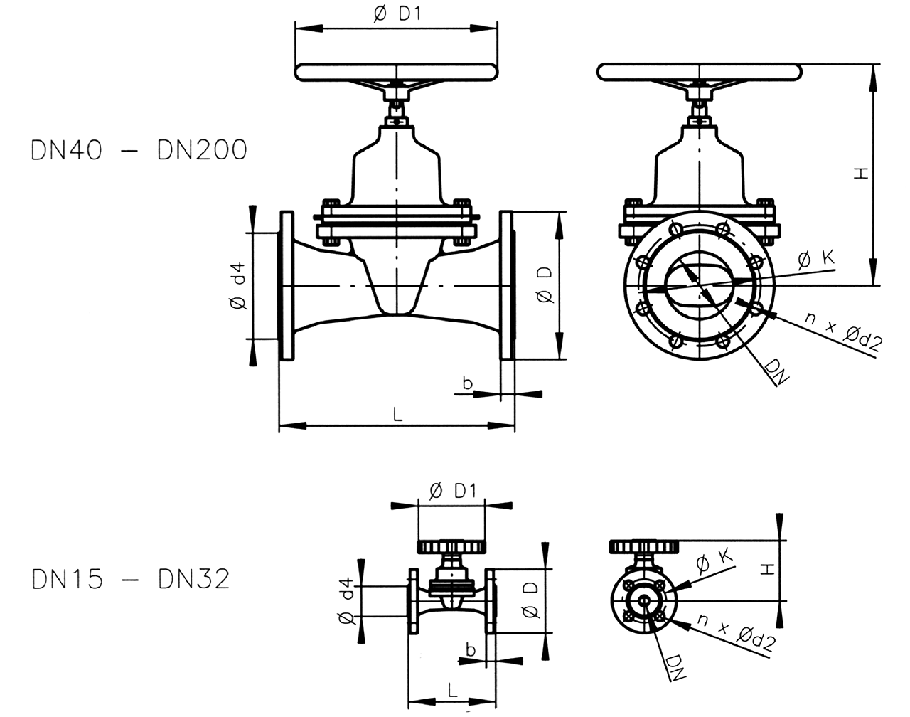
| DN | 15 | 20 | 25 | 32 | 40 | 50 | 65 | 80 | 100 | 125 | 150 | 200 | 250 | 300 | 350 |
| L | 130 | 150 | 160 | 180 | 200 | 230 | 290 | 310 | 350 | 400 | 480 | 600 | 730 | 850 | 980 |
| Ø D | 95 | 105 | 115 | 140 | 150 | 165 | 185 | 200 | 220 | 250 | 285 | 343 | 395 | 445 | 505 |
| Ø K | 65 | 75 | 85 | 100 | 110 | 125 | 145 | 160 | 180 | 210 | 240 | 295 | 350 | 400 | 460 |
| n | 4 | 4 | 4 | 4 | 4 | 4 | 4 | 8 | 8 | 8 | 8 | 8 | 12 | 12 | 12 |
| Ød2 | 14 | 14 | 14 | 18 | 18 | 18 | 18 | 18 | 18 | 18 | 23 | 23 | 23 | 23 | 23 |
| Ød4 | 45 | 58 | 68 | 78 | 88 | 102 | 122 | 138 | 158 | 188 | 209 | 268 | 320 | 370 | 430 |
| b | 14 | 15 | 16 | 17,5 | 17,5 | 19 | 20 | 20 | 21 | 22 | 22 | 29 | 32 | 30 | 33 |
| ØD | 100 | 100 | 100 | 100 | 150 | 175 | 225 | 225 | 300 | 300 | 350 | 400 | 500 | 640 | 640 |
| H | 91 | 105 | 105 | 111 | 167 | 181 | 256 | 263 | 330 | 333 | 381 | 499 | 564 | 700 | 817 |
Weight approx. (kg)
| DN | 15 | 20 | 25 | 32 | 40 | 50 | 65 | 80 | 100 | 125 | 150 | 200 | 250 | 300 | 350 |
| G | 2,5 | 3,0 | 3,5 | 6,5 | 7,5 | 10,5 | 18 | 19 | 28 | 39 | 51,5 | 108 | 170 | 266 | 384 |
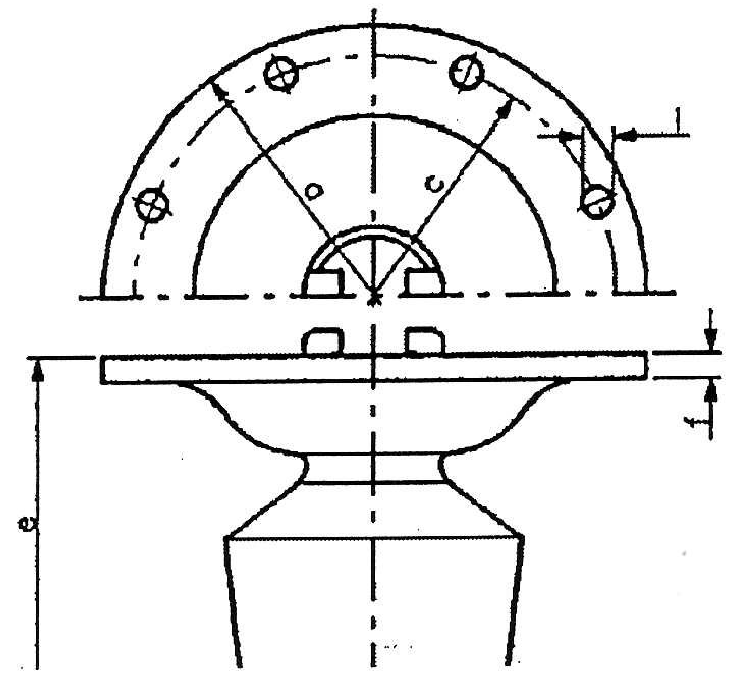
Diaphragms
DN 15 - DN 32
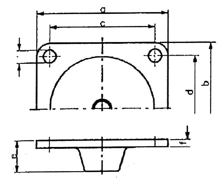
| DN | a | b | c | d | e | f | l | n |
| 15 | 51 | 51 | 38 | 38 | 17 | 4,5 | 5 | 4 |
| 20 | 69 | 63 | 52 | 46 | 21 | 5 | 7 | 4 |
| 25 | 79 | 69 | 62 | 52 | 25 | 5 | 7 | 4 |
| 32 | 94 | 80 | 72 | 58 | 29 | 5 | 10 | 4 |
DN 40 - DN 80
| DN | a | b | c | d | e | f | l | n |
| 40 | 106 | 106 | 84 | 70 | 51,5 | 6,5 | 11 | 4 |
| 50 | 124 | 124 | 100 | 80 | 64 | 7 | 12 | 4 |
| 65 | 158 | 158 | 113 | 113 | 104 | 8 | 12 | 4 |
| 80 | 158 | 158 | 113 | 113 | 110 | 8 | 12 | 4 |
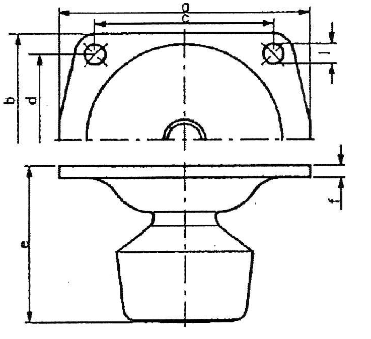
DN 100 - DN 200
| DN | a | c | e | f | l | n |
| 100 | 220 | 194 | 136 | 10 | 12 | 8 |
| 125 | 220 | 194 | 141 | 10 | 12 | 8 |
| 150 | 266 | 240 | 172 | 10 | 12 | 12 |
| 200 | 350 | 310 | 237 | 13 | 16 | 12 |
DN 250 - DN 350
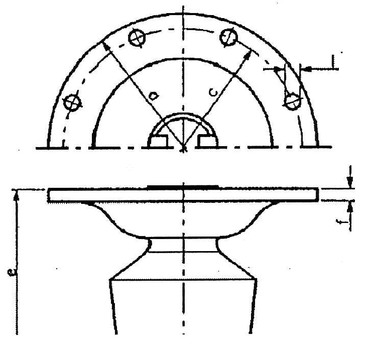
| DN | a | c | e | f | l | n |
| 250 | 400 | 360 | 289 | 15 | 16 | 12 |
| 300 | 470 | 430 | 360 | 16 | 17 | 12 |
| 350 | 550 | 510 | 428 | 17 | 17 | 16 |
Weight approx. (kg)
| DN | 15 | 20 | 25 | 32 | 40 | 50 | 65 | 80 | 100 | 125 | 150 | 200 | 250 | 300 | 350 |
| G | 0,03 | 0,05 | 0,08 | 0,13 | 0,4 | 0,5 | 1,10 | 1,40 | 2,10 | 3,00 | 4,00 | 10,00 | 21,00 | 33,00 | 35,00 |
Technical details subject to change without notice — Tolerances acc. to DIN/ANSI Standards, other dimensions approximate